- Visibility 73 Views
- Downloads 7 Downloads
- DOI 10.18231/j.ijohd.2020.017
-
CrossMark
- Citation
Cone beam computed tomography: A review
- Author Details:
-
Nikita Kapshe *
-
Madhu Pujar
-
Satyam Jaiswal
Introduction
The success in managing endodontic problems is dependent on diagnostic imaging techniques to give critical information about the teeth under investigation, and its neighboring anatomy. Since its initiation, traditional radiography has remained the basis of imaging techniques in Endodontic field. In the modern few decades, on the other hand, advances in medical imaging have been applied, with unstable success, to the various dental applications. Amongst the few specific imaging techniques, that have been researched as prospective diagnostic and treatment planning gear in Endodontics, are digital subtraction radiology (DSR), tuned aperture computed tomography (TACT), ultrasound (US), magnetic resonance imaging (MRI) and computed tomography.[1]
With the newly introduced maxillofacial CBCT in 1996, it has provided us with the first clinically practical technology representative application of 3D imaging for endodontic purposes.[2]
With an ever increasing curiosity in CBCT from various branches of dental field is unparalleled because of its creation of a revolution in maxillofacial imaging, thus providing for the evolution of dental diagnosis from 2D to 3D images and escalating the role of imaging from diagnosis to guidance by images of operative and surgical proceedings through the use of third-party application softwares.[3]
Endodontic implications of CBCT includes that of diagnosis of periapical lesions as a sequelae caused due to pulpal inflammation, identifying and localizing of internal and external resorption, detecting vertical root fractures, the idea of accessory canals, and revelation of the causes of non-healing endodontically treated teeth.[4]
Its exaggerated use has raised several questions regarding the validation and optimization of CBCT exposure that are going to occur during the proceedings, training of CBCT personnel and quality assurances of CBCT scanners. Therefore, it is of prime importance to have a thorough understanding and knowledge about the technical principles for dental CBCT imaging technique and procedures so as to harvest the full profits of this technique while making the radiation related risk to the patient minute.[5]
Limitations of Conventional 2 D Imaging
The reduction of diagnostic outcome of traditional radiography can be accredited to numerous factors, which are stated as follows:
Compression of 3 D structures
Traditional radiography compresses 3 D structures on to a 2 D image.
Anatomical noise
Anatomy in or projected over the area of interest during conventional radiographic imaging may impair visualization of the object under investigation and complicate interpretation of the radiograph.
Geometric distortion
Are the drawbacks of 2 d imaging techniques.[6]
Historical Development of CBCT units
During the early development of CBCT, the technology was being advanced primarily for the dental office. Subsequently, many of the earlier units were modified to include designs that more readily fit within dental offices and clinics. The integration of CBCT imaging in dentistry has in some ways paralleled the transition of panoramic imaging x-ray machines into dental offices. Early panoramic units were mainly sit-down but there was also a lay down unit. Several other sit-down machines were manufactured, but eventually units were made whereby the patient could stand upright for the panoramic exposure. Upright machines became preferable, as it is more convenient and takes less time to transfer patients into and out of these stand-up panoramic units.
The physical size and shape of CBCT units has paralleled this panoramic pathway. One among the very first few available cone beam machines in the market, the New Tom 9000(QR srl, Verona, Italy), was a very large unit that scans the patient lying down in a supine position. This was followed by the New Tom 3G. These earlier generation New Tom units in the long run lost the race to smaller versions, sit-down chair units or to stand-up units. As these smaller units with improved scanner quality could be easily fitted into dental office space with a lower expenditure. In spite of the prior limitations of the NewTom prototypes, CBCT units that scan patients in a supine position have made a return; the NewTom5G (QR srl) and the SkyView (MyRay, Imola, Italy) are currently available. These prototype units have an upright patient loading and also supine position for patient scanning. NewTom also produces standing machines such as the VGi for commercial sales.[7]
Chief Principles of CBCT Imaging Procedure
The beginning of 1990s, saw the dawn of four very important technologic developments that combined to assist assembly of very reasonably priced CBCT units miniature enough to be easily used in the dental office for maxillofacial imaging without taking up to much space:
Introduction of x-ray detectors competent of speedy acquisition of several basic images.
Development of suitably high-output x-ray generators.
Evolution of suitable image acquisition and combination algorithms.
Availability of economical computers potent enough to process the vast amount of acquired image data.

Computed tomographic (CT) scanners most importantly consist of an x-ray source production unit and a detector that is mounted on a rotating gantry. For the entire duration of the rotation of the gantry, the x-ray source leads a creation of radiation, whereas the receptor records the residual x rays after attenuation that occurs by the patient’s tissues that is exposed. These recordings generally comprise the “raw data” that is then reconstructed by a computer algorithm to produce several cross-sectional images. The basic component of these grayscale images is the picture element (pixel) values. The grayscale value or intensity of each pixel is associated to the intensity of the photons incident on the detector. Although providing similar images, CBCT imaging represents a separate evolutionary arm to CT imaging employing multidetector computed tomographic (MDCT) imaging equipment.
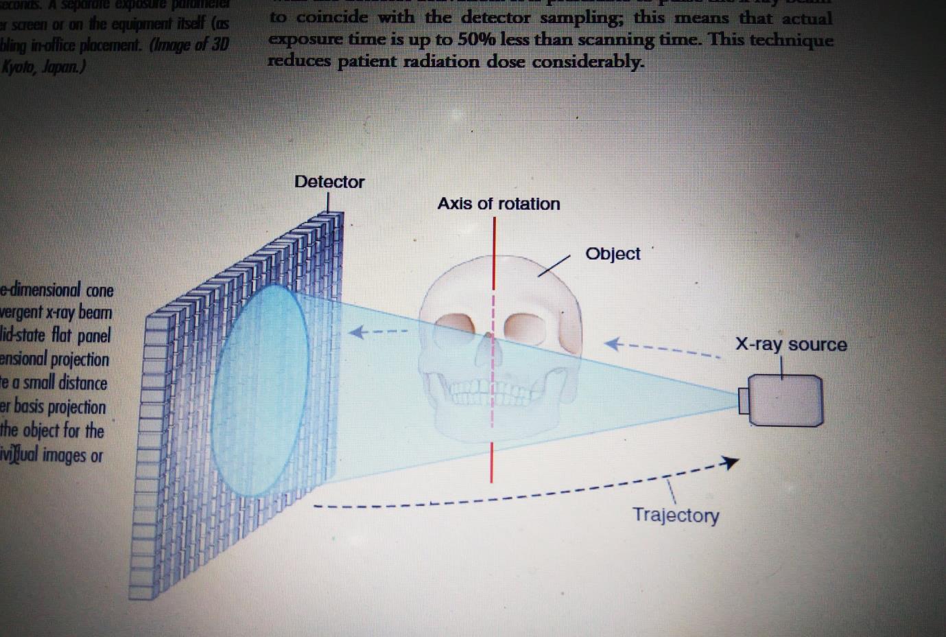
The geometric configuration and acquisition mechanics for the CBCT technique are in theory simple ([Figure 1]).
CBCT imaging is carried out by means of a rotating platform or gantry carrying an x-ray source and detector. A divergent cone-shaped or pyramidal source of radiation is directed through the region of interest (ROI), and the residual attenuated radiation beam is projected onto an area x-ray detector on the opposite side. The x-ray source and detector rotate around a rotation centre, fixed within the centre of the ROI. This rotational centre becomes the centre of the final acquired image volume. During the rotation, multiple sequential planar projection images are obtained while the x-ray source and detector move through an arc of 180 to 360 degrees. These single-projection images constitute the raw primary data and are individually referred to as basis, frame, or raw images. Basis images appear similar to cephalometric radiographic images except that each is slightly offset from the next. There are usually several hundreds of two-dimensional basis images through which the image volume is calculated and constructed. The complete series of images is referred to as the projection data. Because CBCT exposure incorporates the entire ROI, only one rotational scan of the gantry of 180 to 360 degrees that is necessary to acquire enough data for volumetric image construction. Software programs incorporating sophisticated algorithms including filtered back projection are applied to these projection data to generate a volumetric data set that can be used to provide primary reconstruction images in three orthogonal planes (axial, sagittal, and coronal).[8]
Parts of Image Production
There are three key processes to CBCT image production:
X-ray generation
X-ray detection
Image reconstruction
The x-ray generation and detection specifications of currently available CBCT systems reflect proprietary variations in these parameters.[9]
X-Ray Generation
Even though CBCT imaging is technically simple in that only a single scan of the patient is made to acquire a projection data set, numerous clinically important parameters in x-ray generation affect both image quality and patient radiation dose.
Patient stabilization
Current cone-beam machines scan patients in three possible positions:(1) sitting, (2) standing, and (3) supine. With all the machine systems, immobilizing of the patient’s head is more important than positioning of the patient because any head movement degrades the final image.
Regardless of patient orientation within the equipment, the principles of image production will always remain the same.[9]
X-ray generator
During the scan rotation, each projection image is made by sequential, single-image capture of attenuated x-ray beams by the detector. Technically, the easiest method of exposing the patient is to use a constant beam of radiation during the rotation and allow the x-ray detector to sample the attenuated beam in its trajectory. However, continuous radiation emission does not contribute to the formation of the image and results in greater radiation exposure to the patient. Alternately, the x-ray beam may be pulsed to coincide with the detector sampling, which means that actual exposure time is 50% less than scanning time. This technique reduces patient radiation dose considerably. Currently, four units (Accuitomo, CB Mercu-Ray, Iluma Ultra Cone, and PreXion 3D provide continuous radiation exposure. Pulsed x-ray beam exposure is a major reason for considerable variation in reported cone-beam unit dosimetry.
The ALARA (As Low As Reasonably Achievable) principle of dose optimization necessitates that CBCT exposure factors should be adjusted on the basis of patient size.[9]
Volume of scan
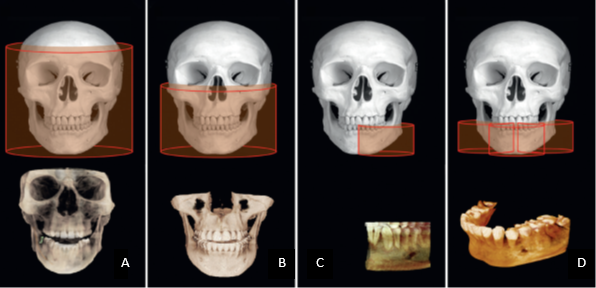
The dimensions of the field of view (FOV) or scan volume that are to be covered primarily depend on the detector size and shape, the beam projection geometry, and the ability to collimate the beam. The shape of the scan volume can be either cylindric or spherical (eg, NewTom 3G). Collimation of the primary x-ray beam limits x-radiation exposure to the region of interest. Field size limitation therefore ensures that an optimal FOV can be selected for each patient, based on disease presentation and the region designated to be imaged. CBCT units are classified according to the maximum FOV incorporated from the scan or scans ([Figure 2]).

They are also classified as:
Small volume (also referred to as focused, small field, limited field or limited volume) systems have a maximum scan volume height of 5 cm.
Single arch CBCT scans have a FOV height of 5-7 cm within one arch.
Inter-arch CBCT scans have a FOV with a height of 7-10 cm.
Maxillofacial CBCT scans have a FOV height ranging from 10-15 cm.
Craniofacial CBCT have a FOV height in excess of 15 cm.[9]
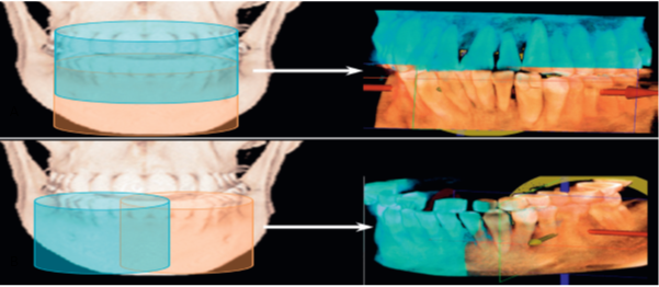
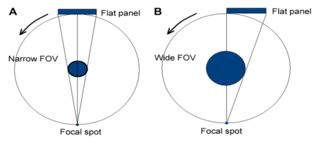
Extended FOV scanning incorporating the craniofacial region is difficult to incorporate into cone-beam design because of the high cost of large-area detectors. Two approaches have been introduced to enable scanning of an ROI greater than the FOV of the detector. One method involves obtaining data from two or more separate scans and super imposing the overlapping regions of the CBCT data volumes using corresponding fiducial reference landmarks (referred to as either “bioimageregistration” or “mosaicing”). Software is used to fuse adjacent image volumes (“stitching” or “blending”) to create a larger volumetric data set either in the horizontal or in the vertical dimension ([Figure 3]). The disadvantage of stitching overlapped regions is that such overlapped regions are imaged twice, resulting in double the radiation dose to such regions. A second method to increase the height or width of the FOV using a small area detector is to offset the position of the detector, collimate the beam asymmetrically, and scan only half the patient’s ROI in each of the two offset scans ([Figure 4]).


Image Detectors
Current CBCT units can be divided into two groups, based on detector type: an image intensifier tube/charge-coupled device (IIT/CCD) combination or a flat-panel imager. The IIT/CCD configuration comprises an x-ray IIT coupled to a CCD by way of a fiber optic coupling. Flat-panel imaging consists of detection of X rays using an ‘‘indirect’’ detector based on a large-area solid-state sensor panel coupled to an x-ray scintillator layer.II/CCD units are usually larger and bulkier and result in circular basis image areas (spherical volumes) rather than rectangular ones (cylindrical volumes) produced by FPDs. Most, but not all, contemporary CBCT units use FPDs. Flat-panel detector arrays provide a greater dynamic range and greater performance than the II/CCD technology. The most common flat panel configuration consists of a cesium iodide scintillator applied to a thin film transistor made of amorphous silicon. Image intensifiers may create geometric distortions that must be addressed in the data processing software, whereas flat-panel detectors do not suffer from this problem. This disadvantage could potentially reduce the measurement accuracy of CBCT units using this configuration. II/CCD systems also introduce additional artifacts.[9]
Voxel size
The spatial resolution—and therefore detail of a CBCT image—is determined by the individual volume elements (voxels) produced in formatting the volumetric data set. CBCT units in general provide voxel resolutions that are isotropic—equal in all three dimensions. The principal determinants of nominal voxel size ina CBCT image are the matrix and pixel size of the detector. Detectors with smaller pixels capture fewer x-ray photons per voxel and
result in more image noise. Consequently, CBCT imaging using higher resolutions may be designed to use higher dosages to achieve a reasonable signal-to-noise ratio for improved diagnostic image quality. Both the focal spot size and the geometric configuration of the x-ray source are important to determine the degree of geometric unsharpness, a limiting factor in spatial resolution. The cost of x-ray tubes—and therefore of the CBCT unit—increases substantially with small focal spot size tubes. Reducing the object-to-detector distance and increasing source-to-object distance also minimizes geometric unsharpness. In maxillofacial CBCT imaging, the detector position is limited because it must be located far enough from the patient’s head so that it freely rotates and clears the patient’s shoulders. Limitations also exist in extending the source-to-object distance because this increases the size of the CBCT unit. However, reducing source-to-object distance produces a magnified projected image on the detector, increasing potential spatial resolution.[10]
Grayscale
The capability of CBCT imaging to exhibit differences in attenuation is linked to the ability of the detector to disclose subtle contrast differences. This parameter is called the bit depth of the system and determines the number of shades of gray available to display the attenuation. All currently available CBCT units use detectors capable of recording grayscale differences of 12 bits or greater. A12-bit detector provides 212 or 4096 shades to display contrast. A 16-bit detector provides 216 or 65,536 shades of gray.[10]

Reconstruction
The reconstruction process consists of two stages, each comprising numerous steps ([Figure 5] ):
Preprocessing stage. The preprocessing stage is performed at the acquisition computer. After the multiple planar projection images are acquired, these images must be corrected for inherent pixel imperfections, variations in sensitivity across the detector, and uneven exposure. Image calibration should be performed routinely to remove these defects.
Reconstruction stage. The remaining data-processing steps are performed on the reconstruction computer. The corrected images are converted into a special representation called a sinogram, a composite image developed from multiple projection images. The horizontal axis of a sinogram represents individual rays at the detector, whereas the vertical axis represents projection angles. If there are 300 projections, the sinogram will have 300 rows. This process of generating a sinogram is referred to as the Radon transformation. The resulting image comprises multiple sine waves of different amplitude, as individual objects are projected onto the detector at continuously varying angles. The final image is reconstructed from the sinogram with a filtered back-projection algorithm for volumetric data acquired by CBCT imaging; the most widely used algorithm is the Feldkamp algorithm. This process is referred to as inverse Radon transformation. When all slices have been reconstructed, they are combined into a single volume for visualization.[11]
Reconstruction times vary depending on the acquisition parameters(voxel size, size of the image field, and number of projections), hardware (processing speed, data through put from acquisition to reconstruction computer), and software (reconstruction algorithms) used [[Figure 5]]. Reconstruction should be accomplished in an acceptable time (<5 minutes) to complement patient flow.[12]
Stages in volumetric data display
The default presentation of the CBCT volumetric data set by most software programs is usually as secondary two-dimensional contiguous reconstructed images in three orthogonal planes (axial,sagittal, and coronal) at a defaulted thickness. Each panel of the display software presents one of a series of contiguous images in that plane. Each image is interrelational such that the location of each image in the sequence can be identified in the other two planes. CBCT data should be considered as a volume to be explored from which selected images are extracted.[9] Technically, four stages provide an efficient and consistent systematic methodologic approach to optimize CBCT image display before image interpretation:
Reorient the data
Optimize the data
View the data
Format the data[9]
Applications in endodontics
Detection of apical periodontitis.
Assessment of potential surgical sites.
Assessment and management of dental trauma.
Assessment of root canal anatomy and morphology.
Diagnosis, assessment and management of root resorption.
Diagnosis of vertical root fractures.
Assessment of the outcome of endodontic treatment.[1]
Limitations
Image noise
The cone-beam projection acquisition geometry results in a large volume of area being irradiated with every basis image projection. A large part of the photons will undergo Compton scattering interactions and will lead to the production of scattered radiation.
Poor soft tissue contrast
Contrast resolution is the ability of an image to reveal subtle differences in image density. Variations in image intensity are a result of differential attenuation of x rays by tissues that differ in density, atomic number, or thickness. [9]
Conclusion
CBCT and its 3D imaging technique tries to overcome the confines of conventional radiography and is a useful accessory to the endodontist’s armamentarium. All endodontists should, thus be well- loaded with knowledge about CBCT and should always liaise with a maxillo-facial radiologist or equivalent specialist when appropriate.
Nowadays, CBCT is a well-accepted diagnostic tool for the care of dental patients. Nevertheless, all radiographic examinations must be reasonable on an person to person basis thereby the remuneration to the patient of each an every exposure must outweigh the risks and in no condition may the exposure of patients to X-rays be well thought-of as “routine,” and definitely CBCT examinations should not be carried out without primarily obtaining a thorough medical history and clinical examination. CBCT should only be thought-of as an accessory to two-dimensional imaging in dental field. Also limited field of view CBCT systems can give images of numerous teeth from just about the same radiation dose as two periapical radiographs, and they may offer a dose saving over multiple traditional images in complex cases.
Source of Funding
None.
Conflict of Interest
None.
References
- Conor Durack, Shanon Patel. Cone beam computed tomography in endodontics. Braz Dent J 2012. [Google Scholar]
- William C. Scarfe, Martin D. Levin, David Gane, Allan G. Farman. Use of Cone Beam Computed Tomography in Endodontics. Int J Dent 2009. [Google Scholar]
- William C. Scarfe, Allan G. Farman. What is Cone-Beam CT and How Does it Work?. Dent Clin North Am 2008. [Google Scholar]
- D A Tyndall, H Kohltfarber. Application of cone beam volumetric tomography in endodontics. Aust Dent J 2012. [Google Scholar]
- R Pauwels, K Araki, J H Siewerdsen, S S Thongvigitmanee. Technical aspects of dental CBCT: state of the art. Dentomaxillofac Radiol 2015. [Google Scholar]
- S. Patel, A. Dawood, E. Whaites, T. Pitt Ford. New dimensions in endodontic imaging: part 1. Conventional and alternative radiographic systems. Int Endod J 2009. [Google Scholar]
- Kenneth Abramovitch, Dwight D. Rice. Basic Principles of Cone Beam Computed Tomography. Dent Clic North Am 2014. [Google Scholar]
- W C Scarfe, Z Li, W Aboelmaaty, S A Scott, A G Farman. Maxillofacial cone beam computed tomography: essence, elements and steps to interpretation. Aust Dent J 2012. [Google Scholar]
- S C White, M J Pharoah. . Oral radiology: principles and interpretation 2014. [Google Scholar]
- . Recommendations of the International Commission on Radiological Protection, ICRP Publication 60. Ann ICRP 1990. [Google Scholar]
- Masahiro Endo, Takanori Tsunoo, Nobuyuki Nakamori, Katsuya Yoshida. Effect of scattered radiation on image noise in cone beam CT. Med Physics 2001. [Google Scholar]
- L. A. Feldkamp, L. C. Davis, J. W. Kress. Practical cone-beam algorithm. J Opt Soc Am 1984. [Google Scholar]
